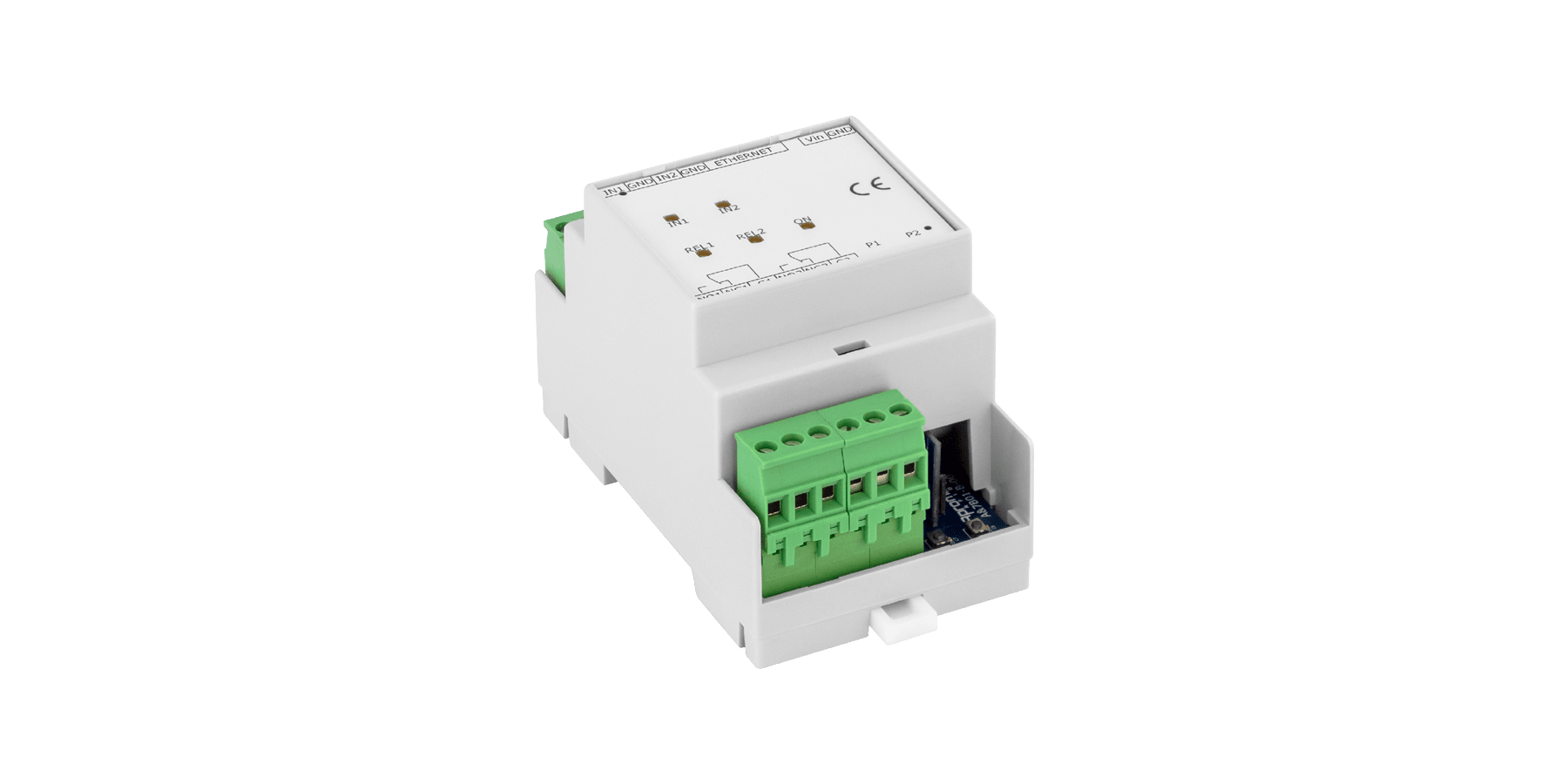
INPUT/OUTPUT MODULES 7B01
2 Relay 2In+2Out Ethernet module.

7B01
MODULES THAT ENABLE THE CORRECT MANAGEMENT OF INPUTS AND OUTPUTS.
Equipped with LEDs on the card to simplify operational diagnostics and for the purpose of indicating: the power supply, the passage of data on the TX and RX lines and, finally, the status of the outputs (each output is associated with an LED). The activation and deactivation of each relay can be programmed at setup, using the buttons on the top of the terminal. The DIN rail housing speeds up installation and maintenance.
| CODE | POWER SUPPLY | RELAY PROTECTION |
| 7B01-L | 12 Vdc | 24 Vdc |
| 7B01-L-P | 12 VDC , PoE standard IEEE 802.3.af | 24 Vdc |
| 7B01-H | 12 Vdc | 230 Vac |
| 7B01-H-P | 12 VDC , PoE standard IEEE 802.3.af | 230 Vac |
| Power supply | 12 VDC +/- 20% | PoE (only with switch cod. 7820) | PoE standard IEEE 802.3.af (version - P) |
| Absorption | Imax = 50 mA |
| Microprocessor | 32 bit RISC CPU with 128kB ROM, 128kB RAM |
| Output | 2 relays 12A 250VAC-contacts C-NC-NO |
| Input | 2 digital input TTL (0-5V) (alternatively, at setup, DO and D1 Wiegand or Clock and Data MagStripe) | 2 buttons |
| Interface | Ethernet |
| Notifications | LED |
| Dimensions | 3M-DIN - 90 x 54 x 60 mm |
| Weight | 125/150 g |
| Material | UL94V0 |
| Colour | Light grey |
| Operating temperature | 0°C /+70°C |